G. Piffer(1), M. Rinaldi (1), B. Della Vedova (2)
(1) Waterstones S.r.l. Via Bolzano/Bozenstrasse 40, 39044 Egna/Neumarkt (Bz) – Italy
(2) Dipartimento di Ingegneria Architettura, Università degli Studi di Trieste, Via Valerio 10, 34127 Trieste – Italy
ABSTRACT
The present contribution is focused on the acquisition and interpretation of geophysical logging in the geothermal well Grado2 under the technical and scientific supervision of the Department of Engineering and Architecture, University of Trieste. The exploitation of geothermal systems in conduction-dominated geothermal requires a robust understanding of the main physical properties of the fractured system, of the saturating fluids and of the water circulation pattern in the reservoir. The Wireline Logging technique, with the registration of complete data sets for petrophysical and geological investigations (Mechanical Caliper, Natural Gamma Ray, Resistivity, Full Acoustic Waveform, Acoustic Televiewer and Spinner Flowmeter logs) complemented with production logs, is a powerful tool for the assessment of these essential parameters.
Geothermal logging results allow to calibrate the geological and geophysical dataset of the area for the geothermal resource assessment and is also useful to select the most appropriate drilling and completion operations for the geothermal well.
Grado2 was adequate to become the production well of the geothermal doublet for the district heating system, whereas Grado1 became the re-injection well into the same reservoir. The Grado Geothermal Pilot Project is an initiative of the Friuli Venezia Giulia Region, Italy, supported by EU funding, for the rational exploitation of geothermal low enthalpy resources contained in deep carbonate reservoirs of the north-Adriatic basin.
1. THE GRADO PROJECT
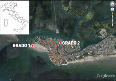
Fig. 1 The Grado Island and the
Grado1/2 well’s location
The Grado project involves the construction of a geothermal pilot plant to heat some public buildings. The geothermal district network is connected to two wells ca. 1,100 and 1,200 m of depth, located within the city center and they are away from each other 1 Km (fig. 1). Distribution network provides geothermal water at 47-49° C transferring heat to the exchangers. The return water from the heat exchangers is collected and conveyed to the re-injection well into the same deep reservoir (Working group DIA-UNITS and FIT, 2014). The Geological Office of the Friuli Venezia Giulia Region and the Municipality of Grado have developed the two main phases of these Geothermal District Heating Project:
• The first phase was aimed at the characterization of the geothermal carbonate reservoir in the Grado area, to estimate its geothermal potential through the execution of geophysical surveys and the drilling of the first exploration well named Grado1; the phase was completed in July 2008;
• The second phase was aimed at completion of geophysical surveys for the location of the second well, the drilling of the well known as Grado2, the evaluation of geothermal potential and the production capacity. Work began in 2012 and were completed in December 2014 – January 2015.
2. HYDRO-GEOLOGICAL SETTINGS
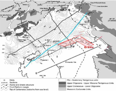
Fig. 2
The Grado Island is located at the south-east of the Grado Lagoon, Provincia of Gorizia, in the Friuli Venezia Giulia Region, Italy. The Friuli plain hosts a complex of confined and unconfined aquifers within an hydrogeological articulated system, developed mainly in N – S direction. The hydrogeological system occupies a heterogeneous sedimentary wedge, characterized by a progressive increase of thickness to W and to the Adriatic Sea where locally exceeds the thickness of 500 m (Della Vedova et al., 2014). This sedimentary wedge consists of the following stratigraphic sequence:
• Plio-Quaternary sediments, deposited in shallow marine, coastal and alluvial environment organized in several transgressive-regressive cycles; the terrigenous cover consists mainly of sandy layers / gravel and silt, with primary porosity extremely variable;
• Alpine Molasse of Oligo-Miocene age, made up of prevailing marl intervals and minor sandstones, deposited in shallow marine environment; characterized by low matrix permeability, but locally affected by systems of fractures and faults;
• Eocene turbiditic Flysch of the Dinaric foredeep consists prevailing marl intervals, rich in deep sea pelagic fauna; with low to very low permeability.
The Cenozoic sediments represent a clastic wedge overlying the Mesozoic limestone platform. Generally the carbonate platform show an articulated morphology, with two clear culminations under the Veneto-Friuli coast. They are bounded by normal fault and transtensional systems deeply rooted in the carbonate basement oriented according to the direction of Southern Alps and Dinaric Chains (Della Vedova et al., 1988, 2008, 2014). Some of these tectonic structures allow the migration of hot mineralized fluids along a crack networks (Della Vedova et al., 2008). In correspondence of the Grado structural high, the carbonate platform is buried under 500-600 m of Cenozoic sedimentary sequence (Fig.2-3, Della Vedova et al., 2008; 2014)
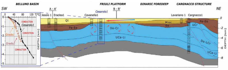
3. GEOTHERMAL MODEL
The platform structural high of Grado host a hydrothermal reservoir porous and fractured allowing the convective circulation of geothermal waters in the first 1-2 km deep (Della Vedova et al., 2014). The convective cells generate higher temperature gradients at the base of the overlying sediments wedge, which contain colder hydrothermal aquifers heated by conduction from the bottom (Figure 2). In this general framework, the Neogene and Paleogene marl sequences can be considered own a very low permeability, and therefore they represent a hydraulic barrier.
4. GRADO 1 AND GRADO 2 GEOTHERMAL WELLS
According to the geological context suggested by the collected multidisciplinary data, the Grado1 well was drilled on the beach, in the west side of the City of Grado, about 100 m from the shoreline. The well intercepted the carbonate reservoir to 618 meters deep and reached a total depth of 1,110 meters (Della Vedova et al., 2008).
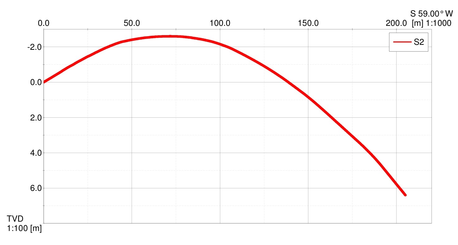
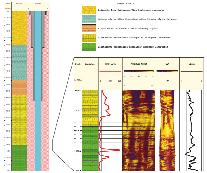
The well Grado2 was drilled on a structural high located in correspondence of the city center (Poletto et al., 2013; Della Vedova et al., 2015), about one kilometer east of the Grado1 well. The drilling program of both wells provided for the adoption of decreasing diameters with depth (24 “, 17” ½, 12 ¼ “, 8 ½”); from ca. 670 m depth, in the upper part of the carbonate reservoir, the hole has been left uncased for the execution of wireline geophysical logs. Steel casing K55 API (20 “, 13” 3/8, 9 “5/8) have been installed and cemented.
The stratigraphy of the Grado1 and Grado2 wells allowed to characterize the geothermal reservoir in the structural highs of the carbonate platform, buried under about 620-670 meters of silicoclastic sediments. The carbonate platform is made up by a thick interval of Paleocene limestone as well by Upper Cretaceous limestone (Fig. 4) The Cenozoic-Mesozoic transition turned out to be well marked in both holes at about 1000 to 1010 m deep by high Uranium’s peaks, also recognized offshore in the northern Adriatic oil wells (Cimolino et al., 2010; Della Vedova et al.,2014).
5. POTENTIAL OF THE GEOTHERMAL RESERVOIR
All data collected have been integrated into a preliminary numerical thermo-fluid dynamic model of and compared with the geological context found on land and at sea, including data from oil and water wells (Della Vedova et al., 2008; et Cimolino al, 2010).
The reservoir is constituted by a confined aquifer fractured, having a salinity of more than 30 ‰ and a temperature of 49.5 ° C at the bottom of the Grado2 well and about 42 ° C in Grado1 well. The geochemical analysis of the geothermal waters indicate that the fluid is anoxic sea water having an age of over 10 million years (Della Vedova et al., 2014).
This means that the geothermal water circulating through a complex network from the oldest Cretaceous limestone to the youngest Paleogene limestone, while the reservoir volume can be estimated at 75-100 km³ (Della Vedova et al., 2014).
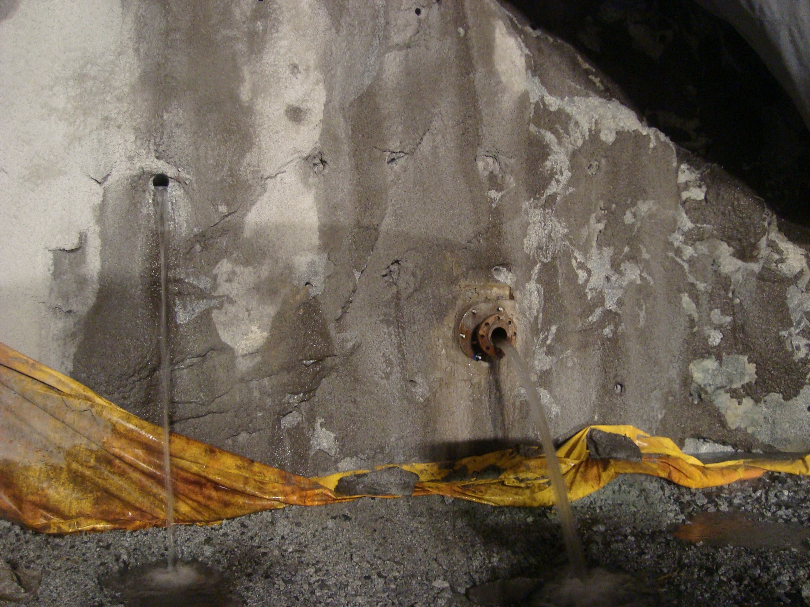
Following two acidification cycles of the well Grado2 was reached an artesian spontaneous outflow of about 100 t/h (laminar flow up to 28 L/s) at a pressure of 240 kPa at the wellhead (Della Vedova et al., 2014). Considering this artesian spontaneous outflow and assuming 20° C as useful difference temperature, the thermal power of Grado2 well turns out to be 2.3 MWth (1700 TOE/h). Because sustainable production was estimated at about 126 t/h (≈35 L/s), the potential heat available is estimated at approximately 3 MWth (2200 TOE/h), (Della Vedova et al., 2014).